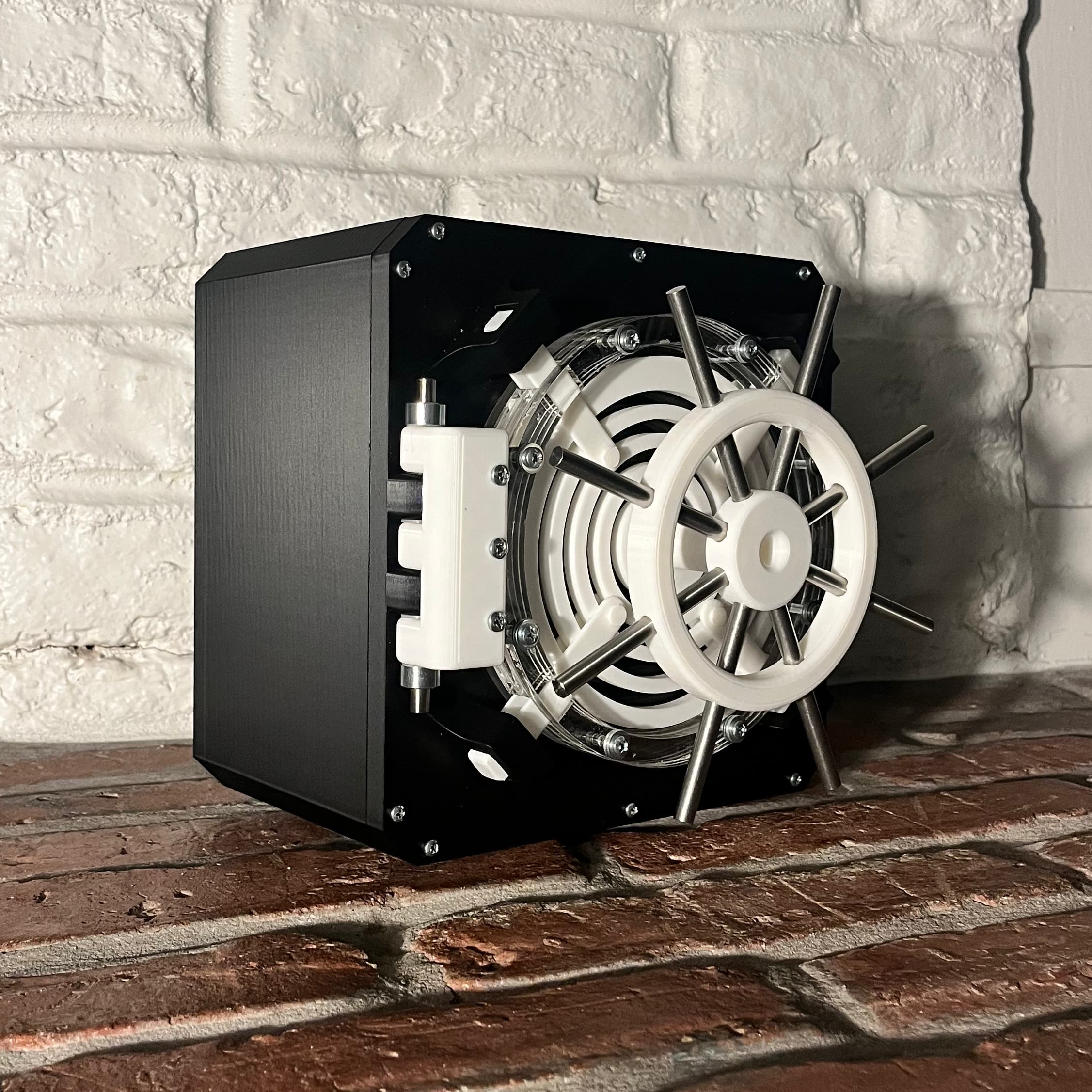
For the second project of ME102: Foundations of Product Realization, you are assigned a mechanism and instructed to build something with it. My group was assigned a 19th-century spiral feed system. We reimagined this historical mechanism as part of a vault door locking system, using the spiral’s gradual rotary-to-linear translation to control four locking arms. This new use-case captures the physical character of the original mechanism while taking it in an unexpected new direction. And it looks fantastic:
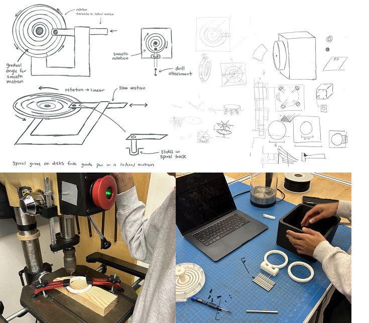
Before any physical experimentation, we sketched and ideated a number of possible mechanical arrangements and functions, with ideas ranging from tidal and wind movement to drills and water wheels. Ultimately though, the idea to transform the drill arm into a lock bolt came from a visit to a restroom in the Cantor Arts Museum. There, we saw the horizontal motion of the stall’s bolt directly creating a fixed rotational change in the external signage (red/green correlating with the stall’s occupied status). Our mechanism performs that same transformation in reverse!
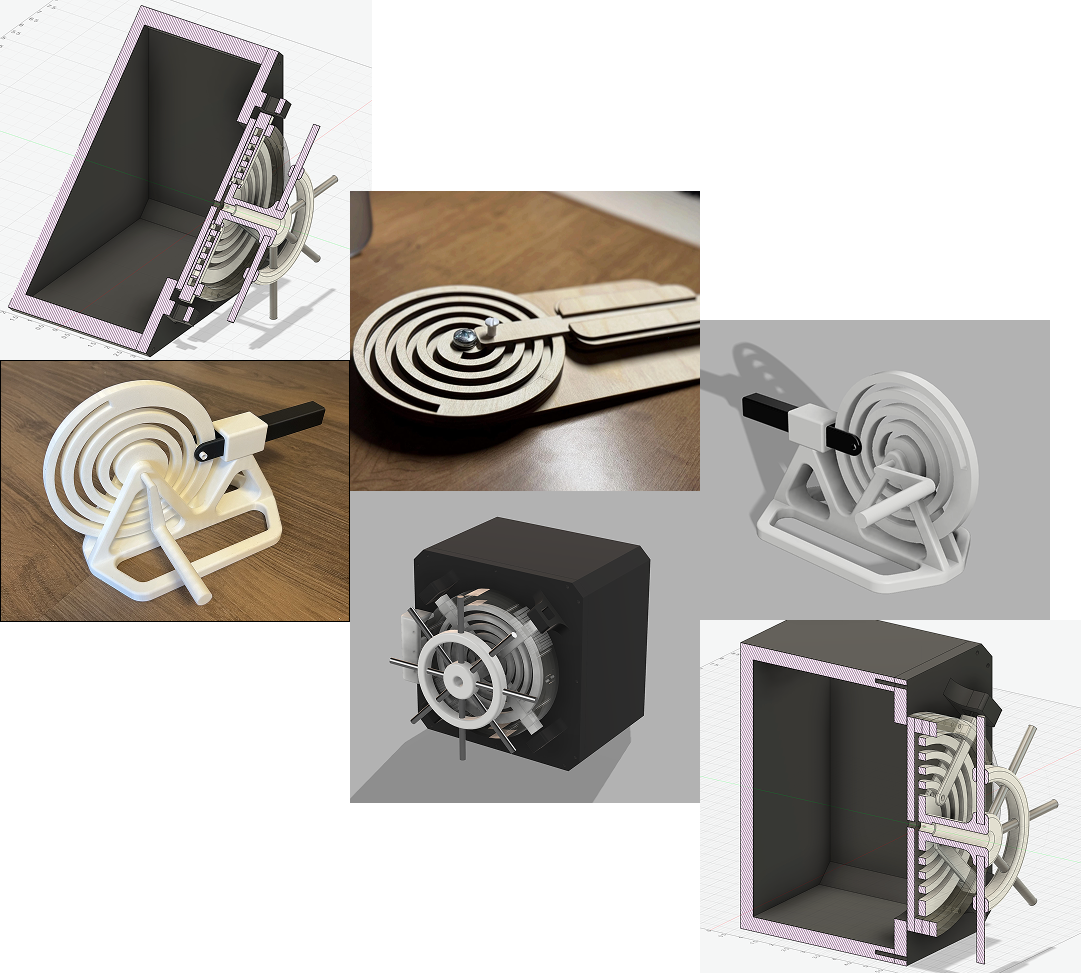
We made two prototypes over the course of the project. The first was a 2.5D laser-cut mock, which we used just to get an intuitive sense of the mechanism. For our second iteration, we migrated to the 3D printer. This version was our first vertical spiral, and the plastic significantly reduced friction over the earlier wood model. It sported a wide base for stability and a LEGO-inspired plus axel to latch the rotational arm to the mechanism. After these two functional experiments, we refocused our work toward building for a specific use-case: the vault.
Our final design built on the successes of our second prototype while upgrading to mixed fabrication methods. This iteration combined a 3D-printed spiral and wheel components with laser-cut acrylic plates and metal fasteners. The inclusion of real hardware allowed for smoother motion, adjustable tolerances, and a sturdier overall assembly. This was a professional device.
Our final CAD model combines four different materials, three manufacturing processes, and two complex joints in one digital source of truth. The device just barely fits inside an 8“ cube (in case you have one of those laying around).
Two interesting notes that might otherwise get missed:
- We designed our 3D printed parts in the center around the 2D constraints of the laser-cut acrylic, which we stacked (0.236” per layer) to create the transparent walls.
- Embedded in a layer of the door’s acrylic and the plastic wall of the safe body are a set of magnets! These add a subtle click that makes the door quite satisfying to open and close.
This project built on a lot of the previous knowledge we had acquired prototyping in ME102. For example, before cutting the final acrylic parts to construct the wall, we performed a number of test cuts to examine the tolerance. This made working with fasteners much easier, and is a practice we adopted after our introduction to friction fits in the first project.
Looking toward the horizon, we are of course interested in improvements to security. That would mean replacing our plastic parts with metal—so that you can’t defeat our vault using blunt force—as well as an actual locking mechanism, which we deemed out of scope for this version. Perhaps you’ll hear more about that from me and my incredible teammates (Vivek and Trun) at some point in the future.